ASTM D7647-10 Ready
The system meets the requirements of ASTM D7647-10, in which oil samples are diluted prior to testing to eliminate interferences from “soft” particles.
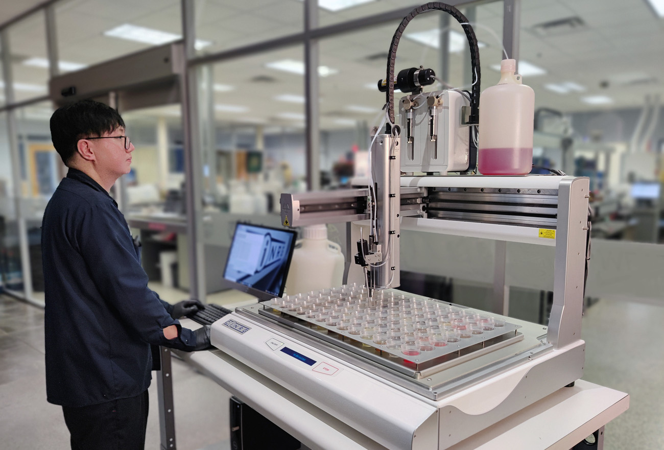
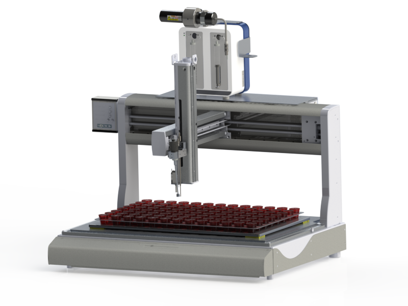
Large-format auto-diluting particle counter for ASTM D7647-10
The first fully automated auto-dilution particle counter purpose-built for ASTM D7647-10 — eliminating soft-particle interference and removing the manual prep bottleneck from high-throughput labs.
The system meets the requirements of ASTM D7647-10, in which oil samples are diluted prior to testing to eliminate interferences from “soft” particles.
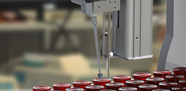
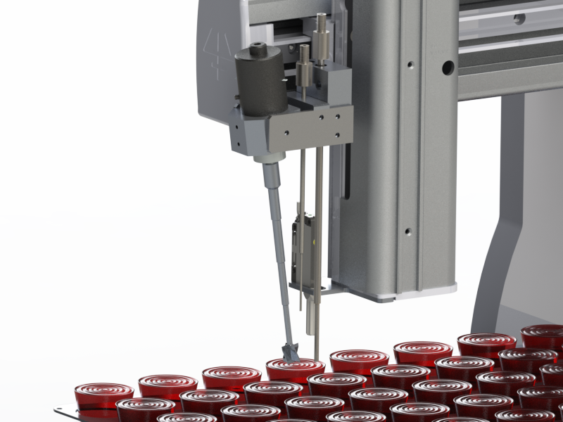
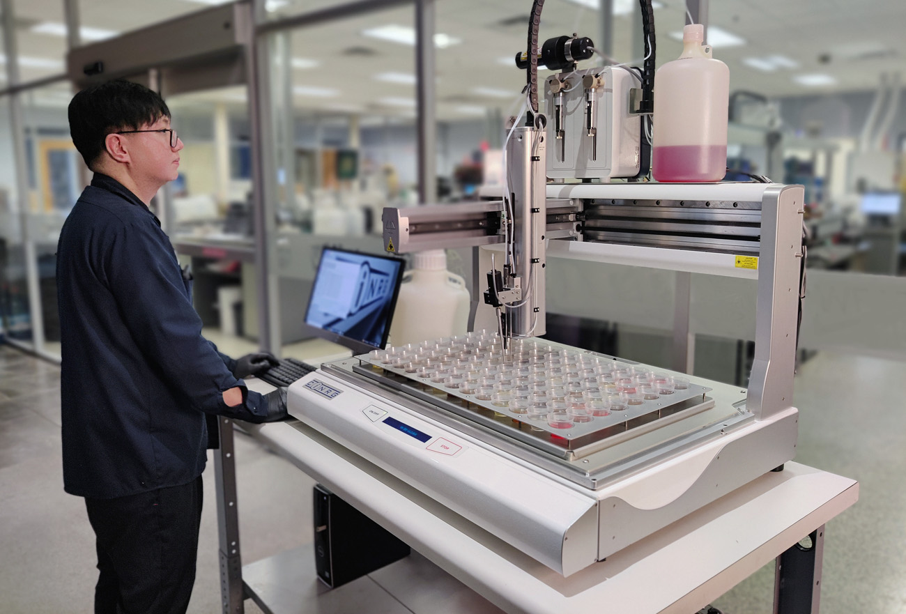
Samples are batched by quickly pouring suitable volumes of homogenized oil into 2 oz (32 ml) sample cups placed in the 104-position sample tray.
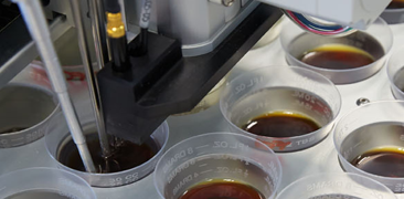
Samples don't require accurate dispensing — the system measures the volume in each cup automatically to an accuracy of ±2% prior to dilution.
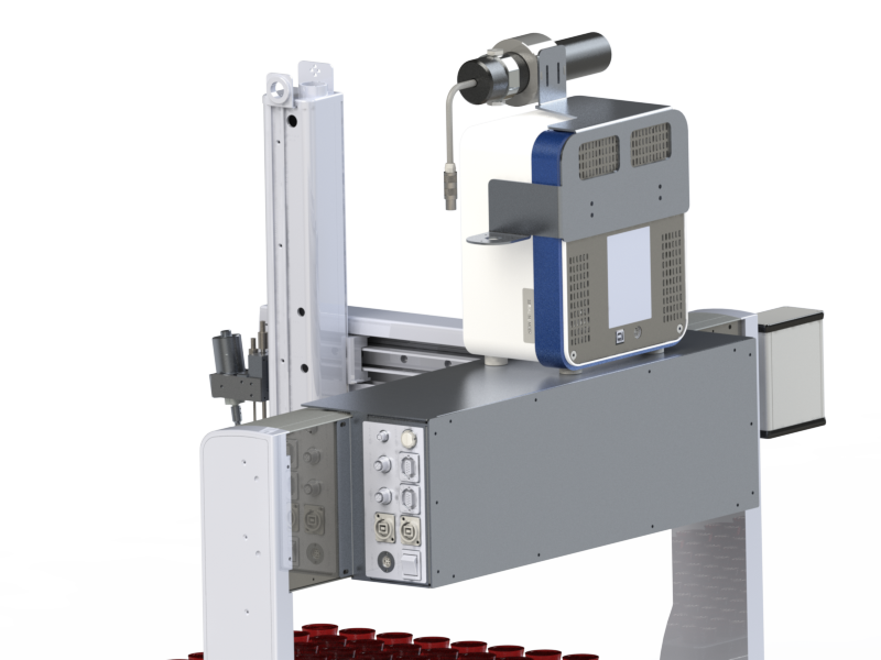
The CS-APC-3 is a fully automated system that meets the requirements of ASTM D7647-10. Oil samples are diluted with solvent prior to testing to eliminate interferences from “soft” particles such as water, varnish, and suspended liquid additives.
The system combines components from several leading equipment manufacturers with innovative technology and sophisticated software developed by WearCheck for use in their oil-analysis laboratory. The system has a high degree of flexibility and can be customized to suit local laboratory processing requirements.
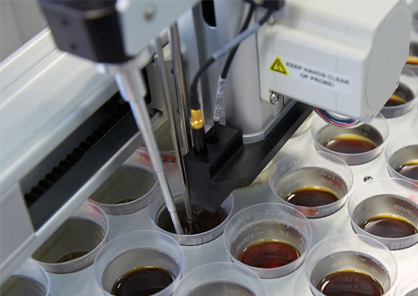
A batch of samples is prepared by pouring suitable volumes of homogenized oil into 2 oz (32 ml) sample cups placed in the 104-position sample tray. Samples don't have to be accurately dispensed — the system measures the volume in each cup to ±2% prior to dilution. Lab technicians control sample dilution by controlling how much oil is poured into the cup, since all samples are diluted to a final volume of 30 ml.
If higher accuracy than ±2% is desired, samples may be pipetted or weighed into the cups, and the sample volume (or weight and density) included in the system's batch file.
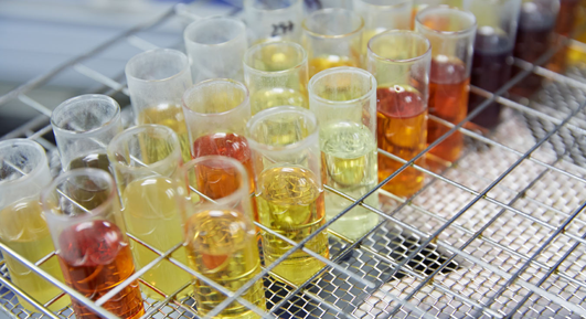
Samples are diluted prior to testing, and dilution ratios can be varied between 1:0 (no dilution) and 1:9 (one part oil, nine parts solvent). A 1:4 dilution, for example, is more than adequate for an oil sample with a viscosity of 1,000 cSt @ 40°C.
Samples can be processed without dilution if required, but viscosity should be ≤46 cSt for that workflow.

A batch file containing both sample information and processing parameters drives the application software. It can be created within the software or imported from CSV. Sample information includes ID, tray position, and optionally a sample volume or weight and density — if those are blank, the system measures the cup volume before dilution.
Processing parameters control how each sample is prepared: stir speed and duration, degas behavior, report format (ISO 4406 or AS4059). Parameters are typically 1–4, with the actual values defined in system parameters editable by the end user (e.g., stir times of 1, 2, 3 mapped to 15, 20, 30 seconds).
Before any testing, the cleanliness of the dilution-solvent batch is determined to obtain the count data later used to correct results for the effects of dilution. When selected in the application software, solvent verification runs automatically: solvent is loaded into position 1 (system flush) and position 2 (measurement). Several measurements are taken and validated against user-editable system parameters.
When sufficient data has been collected, average count values are calculated from valid measurements and stored as the solvent background counts for subsequent calculations.
| Sample throughput | 3.5 min/sample (6 hrs for a complete 102-sample tray)* 130–140 samples per 8-hour shift* |
| Solvent usage | 35 ml/sample** |
| Sample batch size | 102 samples (104-position tray; pos 1 = cleaning beaker, pos 2 = verification solvent) |
* Throughput rate is directly dependent on the settings of the processing parameters; specification stated is using default parameters.
** Solvent usage depends on dilution ratios and processing parameters; specification stated is for 1:1 dilution using default parameters.
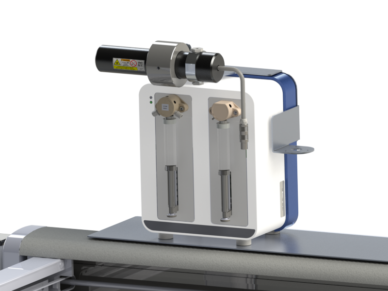
| Model | KLOTZ LDS 45/50 Laser Sensor |
| Measuring range | 4µm to 70µm (3µm to 200µm oil calibration range) |
| 4µm co-incidence threshold | 25,000 particles/ml (undiluted sample) 50,000 particles/ml (1:1 dilution) |
| Cell dimensions | 450µm × 500µm |
| Flow rate | 10 to 50 ml/min (CS-APC-3 calibrated at 30 ml/min) |
| Model | KLOTZ USB Counter |
| Number of channels | 4,096 |
| Model | Baumer UNKC 09 |
| Accuracy | ±0.1 mm from 3 mm to 150 mm |
| Dimensions | 35″(W) × 30″(H) × 38″(D) (89 cm × 76 cm × 97 cm) |
| Weight | 150 lbs (68 kg) |
| Voltage requirement | 100–120–230/240 VAC selectable, 50/60 Hz |
| Input current | 6.0 A @ 100 V · 5.0 A @ 120 V · 2.6 A @ 230 V · 2.5 A @ 240 V |
Protected by patents US 9,164,019 · US 8,689,651 · CA 2,791,003 · CA 2,809,251 · UE 2,912,473. Other patents pending.
Common questions about the large-format auto-diluting particle counter.
The CS-APC-3 is the current production successor to the CS-APC-2. Both meet ASTM D7647-10 with the same KLOTZ LDS 45/50 sensor, 4–70µm range, and 104-position sample tray. The CS-APC-3 introduces refinements in robotics, software workflow, and on-site calibration support. Customers running CS-APC-2 instruments continue to be fully supported — the methodology and calibration fluids are common across the line.
About 6 hours at default parameters — 3.5 min/sample. A typical commercial lab loads two trays per shift to reach 130–140 samples in 8 hours. Throughput is parameter-driven; if your method allows shorter stir/degas/cleaning cycles, the per-sample time drops accordingly.
Yes. Sample batch files are CSV and can be generated by any LIMS or by Excel. Each row carries sample number, tray position, processing parameters, and optionally sample volume or weight/density. Result output is also CSV in user-configurable format — ISO 4406, AS4059 differential and cumulative, NAS 1638, raw count data at 4, 6, 14, 21, 38, 70µm, plus solvent background and dilution ratio. Output paths and naming follow LIMS conventions.
Yes. CINRG provides a low-cost calibration hardware kit (CS-CFSK-3), a CINSTAN calibration-fluid kit (CS-CINSTAN-CFK), a detailed SOP, and an automated Excel calculation template. A trained technician can perform the annual sizing-calibration without sending the instrument back to CINRG. The procedure follows ISO 11171:2022 Annexes A–E plus the laboratory sizing calibration in Section 6.
The system applies a configurable PCS suffix to identify process-control samples. Their counts are compared against user-defined upper and lower limits in the 4, 6, and 14µm channels. PCS samples typically run at the start and end of a batch. If a PCS fails, system parameters control whether the run continues, halts, or quarantines the trailing samples. The CS-APC-3 also enforces ASTM D7647 internal-variance limits (IVL) per run with PASS/FAIL reporting alongside counts.
Field experience suggests 10–15+ years of routine production with annual calibration and standard preventive maintenance. The CS-APC-2, the predecessor of the CS-APC-3, has a documented record of over 80,000 samples on a single instrument at OelCheck Germany at approximately 5,000 samples/month. The CS-APC-3 is built around the same proven KLOTZ sensor and Zaber robotics, so equivalent or longer service life is expected.
The instrument is designed for petroleum-based and aqueous-based oil-analysis samples. It can process samples at viscosities up to 1,000 cSt @ 40°C with appropriate dilution (a 1:4 dilution is more than adequate). Samples below 46 cSt can be processed neat. Samples that arrive with extreme contamination (ISO codes > 27/25/23) are still processable but may require manual high-dilution mode. The CS-APC-3 is not designed for solid-particle suspensions, slurries, or non-fluid samples.
Each delivery includes installation, on-site commissioning, operator training, the calibration SOP, and method-validation guidance. CINRG’s technical team is available for ongoing support by email and phone, and the system can be configured to local laboratory processing requirements at install time. Contact CINRG for service-level details specific to your region or dealer.
Tell us about your throughput, your test methods, and your facility. A CINRG engineer will help you scope the right configuration — and put you in touch with your nearest dealer.